7.3. Design options and mitigation measures#
There are several options in design to take care that a dike is safe with respect to backward erosion piping. Their application depends on the local conditions in terms of the geology, the available space or the level of reliability required. Below we will introduce the most common techniques for backward erosion piping in terms of preventive and permanent design measures; temporary emergency measures will be discussed in section 7.4.
7.3.1. Length of the seepage path and berms#
As the assessment models by Bligh and Sellmeijer indicate, the seepage length (\(L\)) is an important factor in piping safety, as it directly influences the average hydraulic gradient over the structure (\(L/H\)), which is the driving force of the seepage. Longer seepage lengths imply smaller average gradients and, hence, greater safety with respect to piping. Consequently, a classical design measure is increasing the seepage length by means of a landside berm, as illustrated in Figure 7.9.
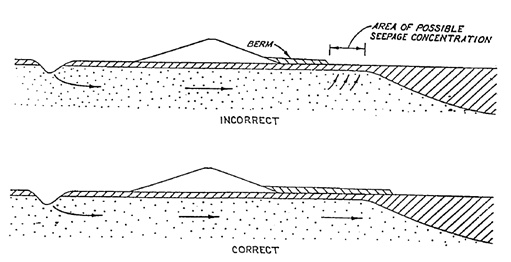
The general rule for determining the required length (and height) of a piping berm is that it needs to long enough to remedy at least one of the sub-mechanisms involved (i.e. uplift, heave or piping). Taking care of at least one sub-mechanism is sufficient as all mechanisms need to occur in order to produce piping failure as explained in section 7.2.6 (i.e. parallel system).
An alternative to constructing landside berms is taking care that sufficient length of the (waterside) foreshore is impermeable, and thus impeding the entrance of seepage water. A longer foreshore also results in an increased seepage length.
7.3.2. Drainage and filters#
In contrast to the berms, which act essentially as counter-weights for the pore water pressures in the subsoil, drainage systems with or without filters try to release these pressures under controlled conditions, such that no erosion can take place. Figure 7.10 shows an example of a drainage trench at the landside toe with a filter covering the bottom of the trench.
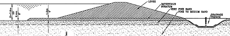
The two main categories of granular filters are geometrically closed and geometrically open. Geometrically closed filters are built up in layers from fine to coarse material ensuring that the particles of the material to be held back cannot permeate through the matrix of the subsequent layer (in the direction of the flow). Often, also geotextiles are used as first filter layer and then covered by coarse and permeable material such as gravel. For details on filter characteristics and design refer to the International Levee Handbook [] or the Dutch recommendations on filters in hydraulic engineering (CUR 161).
7.3.3. Relief wells#
Relief wells are a special category of drainage systems. The wells are inserted in the ground vertically by drilling techniques in order to permeate the aquifer. The seepage water then flows towards and into the relief well, thus relieving the pore water pressure (piezometric head) in the aquifer (see Figure 7.11).
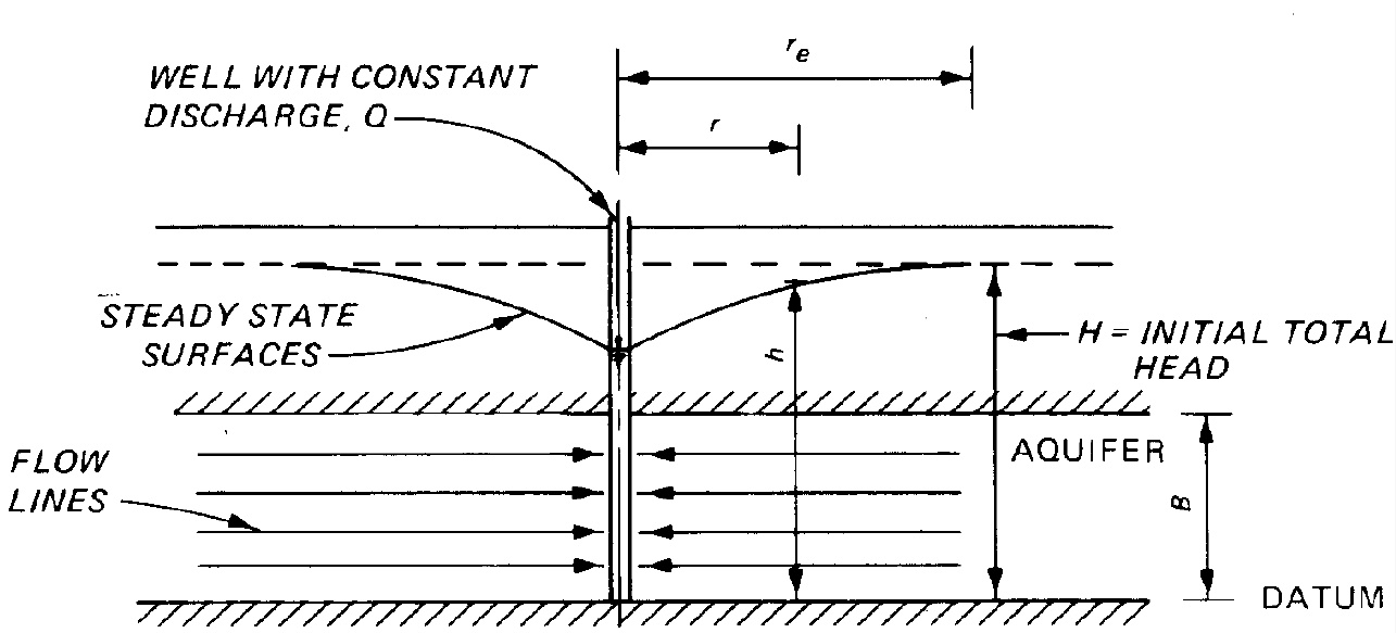
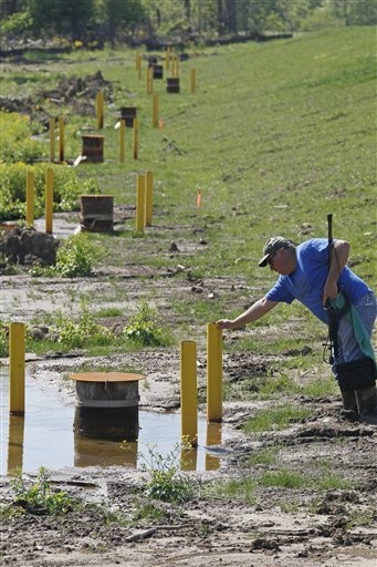
Since the effect of head reduction vanishes with increasing distance from the well, the wells are typically installed in a row parallel to and close to the levee toe, where the danger of uplift and heave is greatest. Needless to state that also relief wells need to be considered as filters and designed such that no transport of granular material can take place. For more information on types of wells and design considerations refer to (USACE, 1986). Miranda (2014) also shows how relief wells can be designed probabilistically.
7.3.4. Cut-off walls#
Cut-off walls are (water-)retaining walls in the longitudinal direction of a dike or levee, penetrating into the aquifer under the dike base. Their purpose is to reduce the groundwater flow velocities by elongating the seepage path or to block (i.e. cut off) the seepage in the dike cross section entirely.
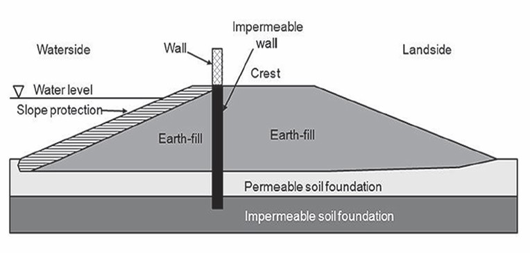
Besides for internal erosion problems, cut-off walls are usually also beneficial for the geo-mechanical stability both as quasi retaining walls as well as through reduced pore pressures in the region of the dike toe as indicated in Ch:Stability on stability.